GLMoM Tutorial - Double Stub Bandpass Filter
In this tutorial we will learn:
First run GLMoM.
The file d-tee.raw to be imported is located in the [glmom]\samples\d-tee directory while [glmom] denotes the installation directory of GLMoM. Since the length unit used by this file is mm while GLMoM uses meter as length unit, the coordinates need to be scaled by 1e-3.
To specify the scaling factor when importing RAW files, choose 'Configure/Import', and fill the dialog box.
To import d-tee.raw, choose 'File/Import/RAW'. The triangular mesh will be imported and displayed.
To rotate, right click and drag mouse.
To zoom in to an area, click the button
![]() . The cursor will
change to
. The cursor will
change to ![]() . Drag a
box with the mouse.
. Drag a
box with the mouse.
To zoom out to the entire object, click the button
![]() .
.
After rotating and rooming, the window can be like this:
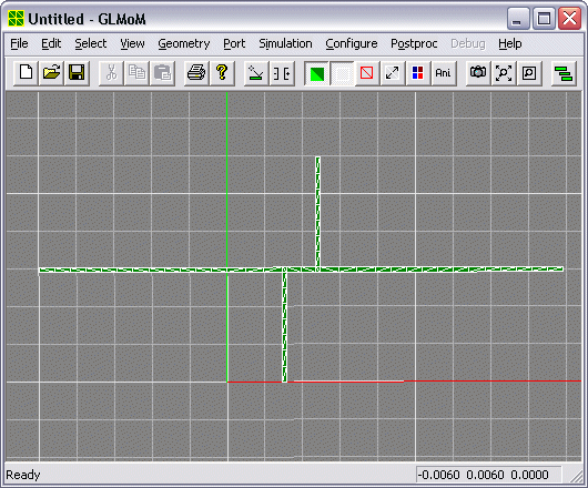
The red line is x axis and the green line is y axis. The grid size is now 1mm and can be changed by choose 'Configure/Geometry'.
Choose 'Simulation/Green's func/Multilayered/DCIM Same Layer', a dialog box will show up as follows.

The file d-tee.med contains definition of the layered medium. You can click the '...' button to select the correct file, and the path for the medium file will be update. It is suggested to use full path for medium file, otherwise GLMoM may not find the file.
The 'Components' radio buttons specifies which components of the Green's functions will be calculated. Use 'HED and VED' only when your structure contains vertical triangles since it will increase the computation burden. For this structure since it is flat, we only need to use HED.
'DCIM end' and 'DCIM images' are control parameters for DCIM (discrete complex image method). Generally you can use the default values.
If you want to check the accuracy of DCIM you can enable the 'Test' check box, but it will increase computation burden.
You can click the 'Edit Src' button to bring up notepad to edit the medium file directly, or click 'Edit' to pop up a dialog box to edit the medium file graphically.
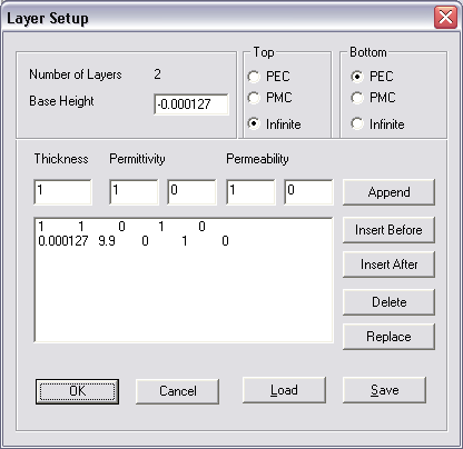
The length unit is meter. This dialog box defines a grounded substrate. 'Base Height' specifies the z coordinate of the ground. The thickness of the substrate is 0.000127 meter, and its complex relative permittivity is (9.9, 0), and permeability is (1, 0). The air layer has a virtual thickness of 1 meter but is actually extends to infinity by defining the 'Top' boundary as 'Infinite'.
GLMoM uses delta-gap voltage source to excite an incident wave along the microstrip line. For each microstrip feeding line, there is a delta-gap voltage source which is located near the end of the microstrip line. A delta-gap voltage source can be defined on one edge which runs across the microstrip line, or a group of connected edges which together form a path running across the microstrip line, as shown in the following figures, where the pink triangles indicate the selected edges for defining the delta-gap voltage sources.


To calculate the S-parameters, we need to define a portion of the microstrip line on which we will observe the current distribution and extract the incident and reflected waves. Therefore for each feeding line, we need to define a delta-gap voltage source, and a portion of the line, we call this data structure a wave port.
To define a wave port, first choose 'Select/Edge'. Then click the edge at where you want to add the delta-gap voltage source. If the edge is selected, it will be indicated by a small pink triangle. The triangle should point to the direction of the incident wave. You may need a little practice to get it right. The correct selection is shown as the above figures.
After selecting the correct edge, then choose 'Port/Add'. The color of the pink triangle will become dark blue, which means there is a delta-gap voltage source defined there.
Do the same thing for the feeding line at the right hand side. The final structure will look like the following figure.
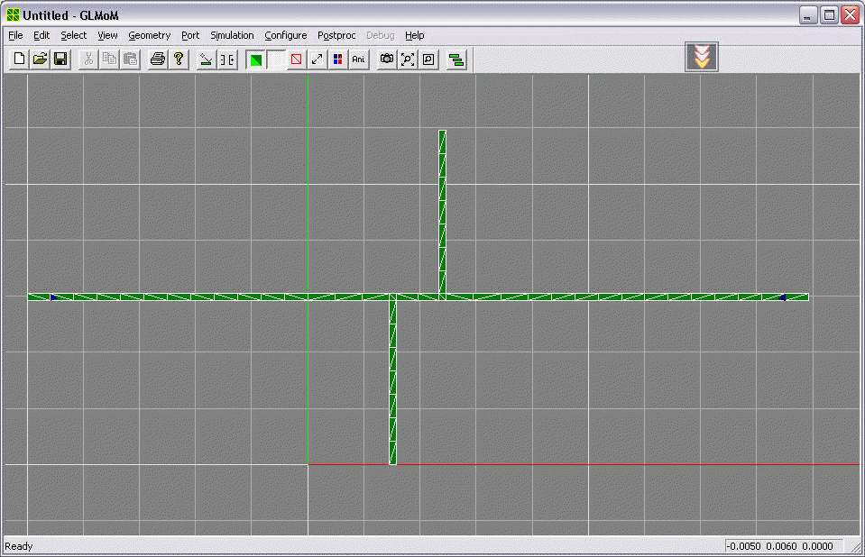
If your ports are added to wrong locations, you can use 'Port/Clear' and add them again.
Choose 'Simulation/Port', a dialog box will show up.
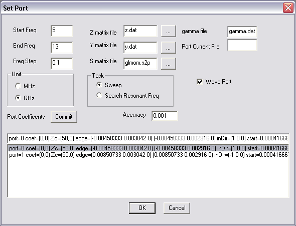
The upper part of the dialog box is easy to understand. It is very important to enable the 'Wave Port' check box for desired results.
The lower half of the dialog box contains a combo box which defines the parameters for the wave port, especially, the portion of the microstrip lines for extracting incident and reflected waves. It is very important to set them to the correct values.
Clicking the combo box will bring the parameters up to the edit box. You can modify them, and then click 'Commit' button to update the values in the combo box.
For example, the default value of the first record is
port=0 coef=(0,0) Zc=(50,0) edge=(-0.00458333 0.003042 0) (-0.00458333 0.002916 0) inDir=(1 0 0) start=0.000416666 end=0.00458333 ref=0.00458333
It is explained as follows:
For this tutorial, we can just use the default values.
After setting the parameters correctly, click 'OK', the simulation will start, and the results are saved to the specified files.
After the simulation, animation showing the current is automatically started. You can press the 'Ani' button to stop the animation, and press the current button to toggle the display of current.
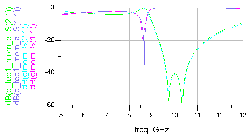
The calculated S-parameters are displayed in the following figure and compared with ADS results. The GLMoM results seem not as sharp as ADS results, but this is caused by insufficient sampling points. The results agree with each other quite well. The archived ADS project can be found in the [glmom]\samples\d-tee directory.
